

Victron
Victron Energy - VE.Bus BMS V2
Victron Energy - VE.Bus BMS V2
Couldn't load pickup availability
VE.Bus BMS V2: Advanced Battery Management for Optimal Protection
The VE.Bus BMS V2 stands as a pinnacle of battery management systems, expertly crafted to interface seamlessly with Victron Lithium Battery Smart 12.8V & 25.6V (LiFePO4 or LFP) setups. This system is essential for those utilizing Victron inverters or inverter/chargers equipped with VE.Bus communication, ensuring your energy solutions are both efficient and secure.
Key Features and Functions:
- Comprehensive Monitoring: Vigilantly monitors Victron Lithium batteries for over voltage, under voltage, and temperature anomalies, safeguarding your power system's integrity.
- Proactive Alarms and Controls: Initiates a pre-alarm for imminent cell under voltage scenarios, preventing potential damage by disabling inverting in VE.Bus inverters or inverter/chargers and other loads.
- Charging Regulation: Automatically disables charging through VE.Bus inverters or inverter/chargers and other chargers in response to cell overvoltage or extreme temperature conditions, ensuring your system's longevity.
- Remote Management: Offers the flexibility to disable VE.Direct and VE.Can solar chargers via a GX device, enhancing control over your energy system.
- Multi-Device Integration: Facilitates the control of VE.Bus inverter/charger with various devices, including the Digital Multi Control, VE.Bus Smart dongle, and GX devices.
- Auxiliary Support: Features auxiliary power input and output terminals, allowing a GX device to remain operational during system shutdowns, ensuring continuous monitoring and control.
Unparalleled Cell Protection:
Each Victron LiFePO4 battery cell receives individual attention, protected against over voltage, under voltage, and over temperature. With integrated Balancing, Temperature, and Voltage control (BTV), these batteries connect effortlessly to the VE.Bus BMS, supporting up to a 48V battery bank assembly for expansive energy solutions.
Versatile System Compatibility:
- Broad Voltage Range: Protects 12V, 24V, and 48V systems with an operating voltage range of 9 to 70V DC, catering to a wide array of power requirements.
- VE.Bus Integration: Ensures flawless communication with all VE.Bus products, including MultiPlus, Quattro, and Phoenix inverters, via standard RJ45 UTP cables.
- Flexible Load Management: Utilizes the Load Disconnect output for controlling remote on/off of loads and electronic load switches, enhancing system reliability.
- Pre-Alarm and Charge Disconnect: Manages imminent risks with pre-alarms and charge disconnect outputs, controlling charger operations and integrating with Cyrix-Li relays for comprehensive system management.
Intuitive LED Indicators:
- Enabled (Blue): Indicates active VE.Bus product operation.
- Cell>4V or Temperature (Red): Signals charge disconnect due to cell over voltage or temperature concerns.
- Cell>2.8V (Blue): Denotes load disconnect output status, ensuring real-time system monitoring.
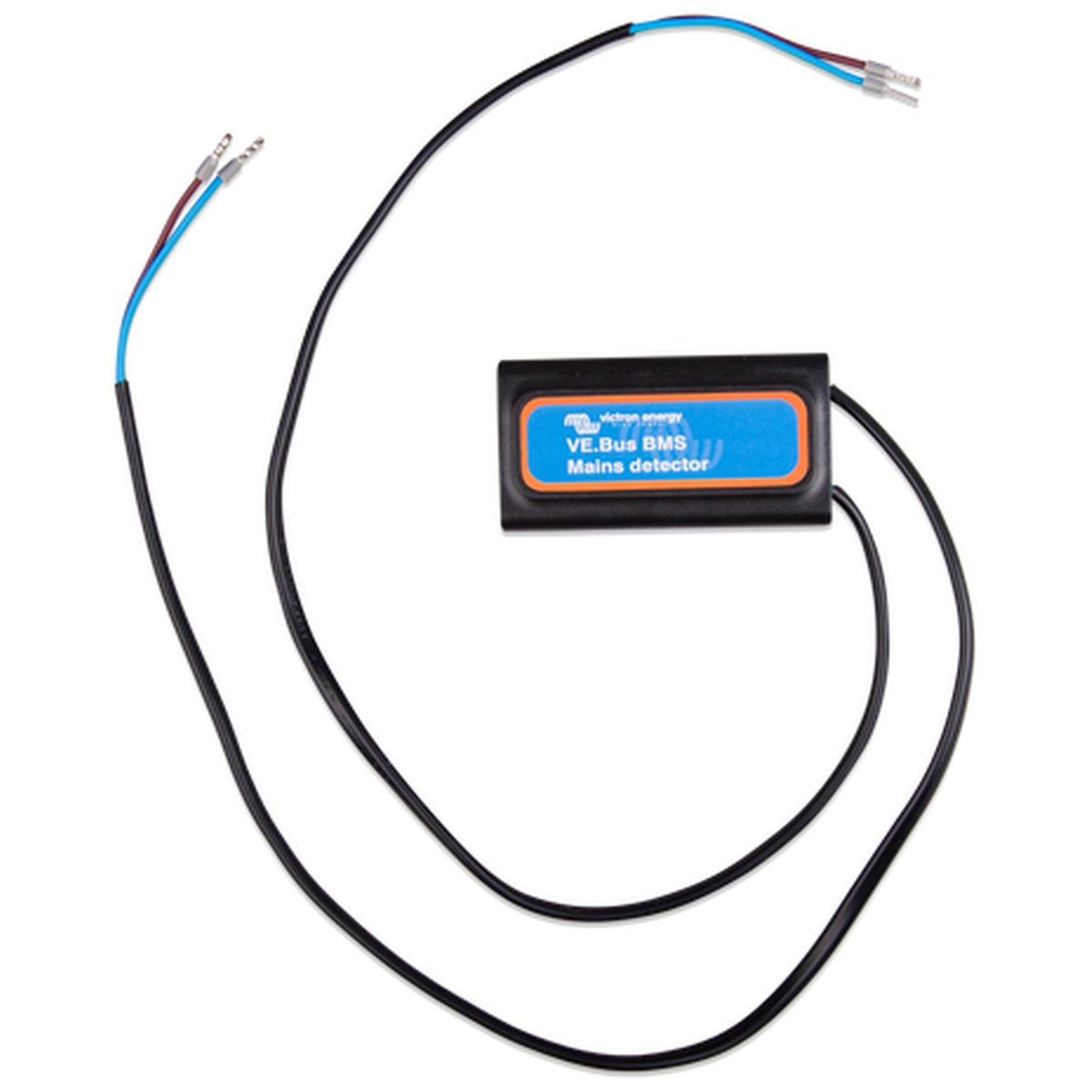
Include VE.Bus Mains Detector
This system includes the VE.Bus BMS Mains Detector, an essential component for seamless integration, except when used with the MultiPlus-II and Quattro-II and the new style MultiPlus 12/1600/70 and MultiPlus 12/2000/80, where it's not required.
Elevate your energy system with the VE.Bus BMS V2, the ultimate solution for safeguarding and optimizing your Victron Lithium Battery setup. Experience the peace of mind that comes with advanced protection, seamless integration, and comprehensive control of your power storage and management systems.
Specifications
| VE.Bus BMS V2 | BMS300200200 |
|---|---|
| Input voltage range | 9 – 70 VDC |
| Current draw - regular operation | 10 mA (excluding Load disconnect current) |
| Current draw - low cell voltage | 2 mA |
| Current draw - switched off via remote on/off terminal | 1.50 mA |
| GX-pow output | 1 A |
| Aux-in input | 1 A |
| Load disconnect output | Normally high (output voltage ≈ supply voltage – 1 V) Floating when the load needs to be disconnected |
| Source current limit | 1 A |
| Sink current | 0 A |
| Charge disconnect output | Normally high, (output voltage ≈ supply voltage – 1 V) Floating when charger should be disconnected |
| Pre-alarm output current rating | 1 A, not short circuit protected |
| Remote terminals | Usage modes to turn the system on or off: a) ON when the L and H terminal are interconnected (switch or relay contact) b) ON when the L terminal is pulled to battery minus (V<3.5 V) c) ON when the H terminal is high (2.9 V < VH < Vbat) d) OFF in all other conditions |
| VE.Bus communication port | 2 x RJ45 sockets to connect to all VE.Bus products |
| Operating temperature | -20 to +50 °C / 0 – 120 °F |
| Humidity | Max. 95 % (non-condensing) |
| Protection grade | IP20 |
| Material | ABS |
| Colour | Matt black with a blue sticker |
| Weight | 120 gr |
| Dimensions (h x w x d) | 23.8 mm x 94.5 mm x 105.5 mm |
| Safety | EN 60950 |
| Emission | EN 61000-6-3, EN 55014-1 |
| Immunity | EN 61000-6-2, EN 61000-6-1, EN 55014-2 |
| Automotive | EN 50498 |
| Min. power rating | 1 A@12 V - If the nominal output voltage is > battery voltage, the AC-DC adapter takes over the power supply of the GX device. |
Share